


贴于背板的复合印刷电路板模块的辐射
日期:2012-06-19
| Radiation from Multiple Printed Circuit Board Modules Attached to a Backplane | |||||||
|
Author: Fred German This FLO/EMC validation note addresses the prediction of the radiated emissions from multiple modules attached to a backplane. Three different configurations of the geometry are presented here. Justification for a simplified model of the printed circuit board is discussed and then results are presented and compared to measured data. The motivation for this validation note, full details on the geometries, and the measurements used for comparison were originally published in [1]. More detailed information about the structures modeled and additional data is available in this reference. Model Details In a real electronic system employing a module in backplane type configuration, the geometry is quite complex involving many geometrically small details such as connectors (and pins), multiple circuit elements on the PCB's, multiple layers in the boards, etc. While in theory this level of detail can be incorporated into a FLO/EMC model for simulation, it would lead to large model preparation and simulation times. A natural question to ask is "How much can the actual structure be simplified for modeling purposes?" In [1], the authors compared measurements for the radiation impedance of a real, fully populated module connected to a backplane to the radiation impedance of a simplified module and backplane configuration. The measurements demonstrated a surprisingly good level of agreement between the two sets of measurements. The simplified geometry treated both the modules and the backplane as conducting plates connected with a wire which served as a connector pin with an attached source. Further justification and discussion of this simplified model, which has been used for the basis of the FLO/EMC simulations presented here, are available in the cited reference.
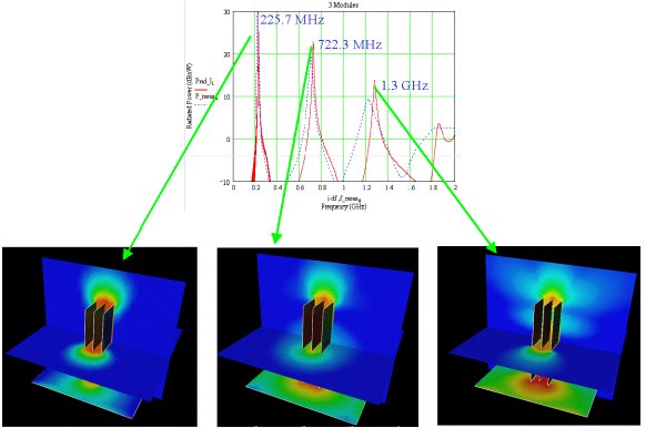
Figures 3 and 4 show (for the three module configuration and at each of the first three frequency peaks) the far-field spherical radiated power pattern (Fig. 3) and the near-field cylindrical power distribution on a cylindrical surface located 3 meters from the structure (Fig 4). This type of data permits the analyst to determine directions of maximum radiation.
Figure 3: Far field spherical radiation patterns for three module configuration at frequencies corresponding to the three highest radiated power peaks.
Figure 4: Near field cylindrical radiation patterns on a surface three meters away from the structure for three module configuration at frequencies corresponding to the three highest radiated power peaks.
Figure 5: Electric field magnitude on orthogonal planes through device and surface currents on the module/backplane structure for three module configuration at frequencies corresponding to the three highest radiated power peaks. Conclusions This FLO/EMC validation note has presented a comparison of measured and simulated data for the radiation from multiple modules connected to a backplane. Agreement with the measurements presented in [1] is quite good with all major radiation features being accurately predicted. Further, examples of the extensive visualization capabilities within FLO/EMC were shown.
Reference |

 沪公网安备 31010602003953号