


FloPCB在线路层次上控制温度
日期:2005-08-25
Get On Board:
Solving THERMAL PROBLEMS at Board Level
The early bird gets the worm. Instead of waiting to address thermal issues at the system
level, tackle them at board . level instead. by ROBIN BORNOFF
大部分印刷电路板设计直到设计程序的后期阶段,元件布局固定而且线路板布线后,才会处理温度的问题。这种方法的问题是,要解决这时出现的温度问题可能会成本高昂,因为可能需要大量变更,如控电板重新设计、电路板布局变更或重新布线。在对成本敏感的产品中,定制或奇特的温度解决方案可能会在设计上花费了可观的时间和金钱后,断送掉设计。本文详细说明在线路板层次上控制温度问题的各种方法,如元件的设计、线路板的温度饱和以及利用嵌铜和不同的封装风格。
Normally, thermal issues are not addressed until the latterstages of the design process, when component placement has been fixed and the board routed. The problem with this approach is that potential thermal issues arising at this pointcan be expensive to resolve, because substantial changes such as cabinet redesign, board placement changes or rerouting may be required. In a cost-sensitive product, the need for custom or exotic thermal solutions may even end up killing the design after considerable time and money have been expended. That’s why it makes sense to perform board-level thermal simulation very early in the design process. This analysis can help highlight potential thermal issues and provide engineers with more flexibility in resolving them, before hundreds of hours of engineering time are invested in unusable designs.
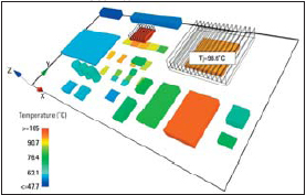
FIGURE 1. A thermal simulation was performed on a board that was designed to add point-to-point optical distribution technology to an existing subrack. The results showed that the processor and chipset in the new design were much too hot, a problem corrected by the relocation of components.
Thermal Density Increases
In the fairly recent past, board-level thermal simulation was considered an unnecessary luxury. Thermal management was usually addressed at the time the chassis was designed, normally by adding fans and cooling vents. Often, this design was based on a system-level simulation. The chassis designed by this method normally has a relatively long shelf life, typically three to five years. Once the thermal solution is fixed, it is expected to last through several generations of boards. In the past, board-level thermal solutions were typically limited to adding a heatsink to thermally critical components. In most cases, this approach was satisfactory because thermal densities were low enough that board redesigns did not have a major thermal impact. But as more speed and functionality are packed into electronic systems, this old approach is becoming untenable. Thermal densities are rising at a rapid pace with each new product generation. Often a chassis design that worked well in the previous generation fails from a thermal standpoint today. In many cases it is necessary to add to the expense and weight of the product by adding a heatsink or fan. Another concern is that adding heatsinks can have secondary effects, such as blocking airflow to downstream components. Sometimes it will be preferable to go back and redesign the chassis or the board layout, adding to engineering costs and potentially causing the product to be delivered late. In any case, the cost of design changes generally increases by an order of magnitude or more as the design moves from conceptual to detailed to validation. Why are thermal management problems typically addressed late in the design cycle system level? One reason is that system-level thermal simulation is the primary method for assessing thermal management. System-level thermalanalysis normally requires the services of a thermal engineer with experience in using the relatively complex software required to simulate a complete electronic system. With a typical ratio of one thermal engineer for every 10-20 electrical engineers, some thermal engineers become overwhelmed with work as more board upgrades require the thermal solution to be reconsidered. The fact that not every board design variation can be thermally vetted results in an increased risk of thermally unviable designs passing to the final design phase. Electronic manufacturers are beginning to address these problems by paying more attention to thermal design at the board level. Often, when designing a new board for an existing enclosure, electrical engineers are simulating the board alone to identify hot spots. Problems identified at this stage can often be addressed by layout changes that can be made nearly without cost at this stage of the process. Board-level simulation tools are usually much easier for EEs to use because they are designed around tools they already use, such as functional block diagrams and physical layouts. 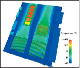
FIGURE 2. Board-level thermal simulation was used early when designing an upgrade to an existing cPCI chassis. The results of the simulation exposed a drafting effect. Engineers were then able to quickly explore other design options.
In a typical board-level thermal simulation process flow, the systems architect will develop the initial concept design by creating a functional block diagram. The hardware design engineer then derives the first physical layout directly from the block diagram. At an early stage in the design process, long before the mechanical engineer gets involved, the electrical engineer can use board-level simulation to evaluate the new board design in an existing system. A 3D computational fluid dynamics solver predicts airflow and temperature for both sides of the board. Often the designer will identify hot spots, and cooling management can thus be considered from the earliest stages of the design process. Changes made to the functional block diagram are instantly reflected in the physi-cal layout and thermal representation. At this stage, far more alternatives exist to deal with thermal problems. Rather than being limited to expensive addons, engineers can consider a wide range of processes such as changing the board layout, adding copper inserts or changing the package style. The board-level model can also be imported into a system-level thermal model, such as the one that may have been created when the original system was designed. This saves the mechanical engineer time in updating the system-level model, if necessary, while reducing the chance of errors caused by miscommunications. The results from the system-level analysis can also be exported to the board-level simulation, making it possible for the electrical engineer to apply the system-level airflow and temperatures to the board being designed. This approach keeps all team members in sync and enables them to contribute to concept development in real time.
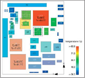
FIGURE 3. Board-level simulation is usually most effective when used early in the development process, but it also provides an effective troubleshooting tool. In this example, board-level simulation was used to troubleshoot an upgraded add-on card.
Layout Modification For Thermal Success
Let’s take a look at how the process of solving board-level thermal issues early works in the real world. A 12.75"x 7" board was designed to add point-to-point optical distribution technology to an existing 1.2"slot pitch subrack containing 14 cards cooled by a fan tray with eight fans (FIGURE 1). The chassis was designed for a previous generation product using system-level thermal simulation so engineers already knew the airflow that goes into the slot where this new board is being placed. When the new board was first conceived, a systems architect defined the functional blocks and connectivity using a board-level thermal simulation tool. The hardware engineer then took over and generated the initial component placement definition. With this information entered, the hardware engineer was then easily able to perform a thermal simulation. The results showed that the 40 W processor and 6 W chipset in the new design were much too hot. With these results in hand, the hardware engineer consulted a thermal engineer, who took possession of the board-level model and tried adding heatsinks to the two hot components. Then the thermal engineer re-ran the analysis and discovered that this approach did not solve the problem because the relatively tall capacitors upstream of the processor were blocking the flow into the processor heatsink. The hardware designer relocated the regulator functional group slightly to allow the airflow full access to the processor heatsink. This initial thermal optimization defined the floor plan as a starting point for the rest of the design process. Board-level simulation was used in the early stages of the design of an upgrade to an existing cPCI chassis (FIGURE 2). The board area was constrained by the form factor to 166 x 230 mm and restricted vertically by the standard 0.8?board pitch. The current platform was tested and shown to provide a slot flow rate of 200 lfm. The speed and the number of interconnects were driving factors in the performance restrictions on the relative component placement. This translated to the physical definition in the pinout and subsequent ability to route the board with the least number of layers. For this board, the most critical nets were those that connect the CPUs, MCH, ICH and memory. Cost restrictions limited the design to four layers, so it was necessary to keep a direct line of sight from the appropriate pin section to the target counterpart. For the purposes of a placement study, engineers used rules of thumb to place the larger components and those that have a fixed position, such as connectors. These are often the same devices included in the functional block diagram. The initial placement put the components with the highest power density at the leading edge of the board. This was the limit of the thermal qualification done at the board design stage before the detailed design work was started on the mechanical design and routing. A board-level thermal tool was used at this stage to accurately evaluate the design from a thermal standpoint. The results of the simulation exposed a drafting effect in which the CPU on the left side preheated the air passing over the DIMM. If this were caught after the detailed design work had begun, the options would have been either to reduce performance in order to drop the power dissipated by this device or to add cost by implementing a thermal solution for the DIMM. By evaluating this in the concept phase, engineers were able to explore other options in a matter of minutes to reduce the risk. Several placement options were simulated. Performing this preliminary thermal analysis made it possible to observe the impact of chosen component placements. Although rules of thumb and intuition are beneficial, many second-order effects such as drafting of components or thermal saturation of the board are difficult to anticipate without analysis. It turned out that in this application, slightly drafting the CPUs provided the ideal solution. Identifying this before investing in detailed routing made it possible to achieve the desired performance without introducing anyadditional costs. In high-volume applications such as this single board computer, removing the need for an expensive solution such as a heat spreader can save millions of dollars in material, manufacturing and qualification costs.
Board-level Troubleshooting
While board-level simulation is usually most effective when used at the early stages of the development process, it also provides an effective troubleshooting tool. Board-level simulation was used to troubleshoot an upgraded add-on card measuring 6.5" x 5.5" (FIGURE 3). The previous platform provided a uniform flow rate of 400 lfm at 35°C and the vertical heatsink volume was constrained by the 25 mm pitch between boards. Engineers modeled the new components using “2 resistor” or “Delphi resistor” models (simplified thermal component models capable of predicting accurate case and junction temperatures), some provided by the vendor and others created by the engineers themselves using a Web service, and added them to a board-level model. The results indicated that two components exceeded their maximum junction temperature and heated up a section of the board, causing a third component to approach its specified maximum temperature. In this case, board placement had been frozen so it could not be used to resolve the problem. In addition, the option of transferring the heat into the board with thermal vias or a local increase in copper content to improve heat spreading did not look like a viable solution. So engineers considered adding heatsinks. In an effort to reduce costs, they placed the same 21 x 21 mm pin fin heatsink on both of the two hot components. Using a thermal interface material reduced thermal resistance between the components and the heatsink. The results of a new thermal simulation with these design changes indicated that with the new design, all components were safely below the 90°C junction temperature limit. Current thermal densities require engineers to consider the mechanical requirements and limitations of the thermal solution in the earliest stages of board design. Although some rules of thumb can be employed in regards to the required volume and drafting effects, they often compete and do not provide accurate enough information for tradeoffs to be considered. These applications demonstrate the benefits of implementing board-level analysis as early as possible in the design cycle. The analysis helps highlight potential thermal issues and provides engineers with more flexibility in resolving them before engineering time is invested in unusable designs. In most applications, the board will continue to evolve, but with collaborative analysis tools engineers can work in cross-functional teams addressing thermal, electromagnetic compatibility, stress and reliability issues until the physical prototype is built and tested to confirm the results of the simulations. PCD&M
ROBIN BORNOFF is a product manager at Flomerics, UK. She can be reached at robin.bornoff@flomerics.co.uk.

 沪公网安备 31010602003953号